NSN 9540-01-496-1448
Part Details | STRUCTURAL BEAM
9540-01-496-1448 A structural shape fabricated from a ferrous or nonferrous material and resembles the following cross-sectional forms: For the letter H, both flanges of the H section are equal or longer than the width measured along the axis of the web; for the letter I, a 16 2/3 percent slope on the inside face of the ferrous type flange, either one or both of the nonferrous type flanges are shorter than the length measured along the axis of the web; for the letters T and Z, on nonferrous type, the web is usually at right angles to the flanges. Letter H section may have a maximum of 5 percent slope on the inside face of the flanges.
Alternate Parts: 1MA160D0510555, 1MA160D05-10555, QQA20011, QQ-A-200/11, AMSQQA20011, AMS-QQ-A-200/11, 9540-01-496-1448, 01-496-1448, 9540014961448, 014961448
| Supply Group (FSG) | NSN Assigned | NIIN | Item Name Code (INC) |
|---|---|---|---|
| 95 | APR 04, 2002 | 01-496-1448 | 37018 ( BEAM, STRUCTURAL ) |
REFERENCE DRAWINGS & PICTURES
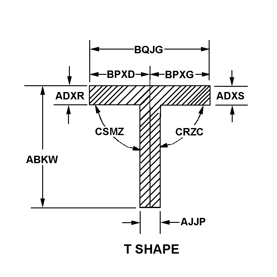
T SHAPE

SQUARE END

SQUARE END

SQUARE END

SQUARE END

Cross Reference | NSN 9540-01-496-1448
| Part Number | Cage Code | Manufacturer |
|---|---|---|
| 1MA160D05-10555 | 76301 | BOEING COMPANY, THEDBA BOEING |
| QQ-A-200/11 | 81348 | FEDERAL SPECIFICATIONSPROMULGATED BY GENERAL SERVICES |
| AMS-QQ-A-200/11 | 81343 | SOCIETY OF AUTOMOTIVE ENGINEERS INC |
Technical Data | NSN 9540-01-496-1448
| Characteristic | Specifications |
|---|---|
| MATERIAL | ALUMINUM ALLOY 7075 |
| MATERIAL DOCUMENT AND CLASSIFICATION | QQ-A-200 TO 11 FED SPEC 1ST MATERIAL RESPONSE |
| FABRICATION METHOD | EXTRUDED |
| HEAT TREATMENT | T-73511 SOLUTION HEAT TREATED |
| LENGTH | 10.000 FEET MINIMUM AND 12.000 FEET MAXIMUM |
| BASIC SHAPE STYLE | T SHAPE |
| OVERALL HEIGHT | 1.250 INCHES NOMINAL |
| LEFT SIDE TOP FLANGE THICKNESS | 0.080 INCHES NOMINAL |
| RIGHT SIDE TOP FLANGE THICKNESS | 0.080 INCHES NOMINAL |
| LEG THICKNESS | 0.180 INCHES NOMINAL |
| LEFT SIDE TOP FLANGE DISTANCE TO CENTER OF BOTH FLANGES | 1.080 INCHES NOMINAL |
| RIGHT SIDE TOP FLANGE DISTANCE TO CENTER OF BOTH FLANGES | 1.280 INCHES NOMINAL |
| TOP FLANGE WIDTH | 2.360 INCHES NOMINAL |
| LEFT TOP INSIDE ANGLE | 90.0 DEGREES NOMINAL |
| RIGHT TOP INSIDE ANGLE | 90.0 DEGREES NOMINAL |
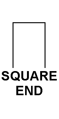
| FIRST TIP STYLE | SQUARE END |
| SECOND TIP RELATIONSHIP TO FIRST TIP | IDENTICAL |
| THIRD TIP RELATIONSHIP TO PRECEDING TIPS | IDENTICAL W/FIRST TIP |
| WEIGHT PER UNIT MEASURE | 0.404 POUNDS PER LINEAR FOOT |
| SPECIAL FEATURES | ANGLE ENDS ARE RADIUS PER DATA PROVIDED |