NSN 9540-01-469-3308
Part Details | STRUCTURAL BEAM
9540-01-469-3308 A structural shape fabricated from a ferrous or nonferrous material and resembles the following cross-sectional forms: For the letter H, both flanges of the H section are equal or longer than the width measured along the axis of the web; for the letter I, a 16 2/3 percent slope on the inside face of the ferrous type flange, either one or both of the nonferrous type flanges are shorter than the length measured along the axis of the web; for the letters T and Z, on nonferrous type, the web is usually at right angles to the flanges. Letter H section may have a maximum of 5 percent slope on the inside face of the flanges.
Alternate Parts: CVC10010161GA, CVC10010-161GA, 9540-01-469-3308, 01-469-3308, 9540014693308, 014693308
| Supply Group (FSG) | NSN Assigned | NIIN | Item Name Code (INC) |
|---|---|---|---|
| 95 | NOV 12, 1999 | 01-469-3308 | 37018 ( BEAM, STRUCTURAL ) |
REFERENCE DRAWINGS & PICTURES
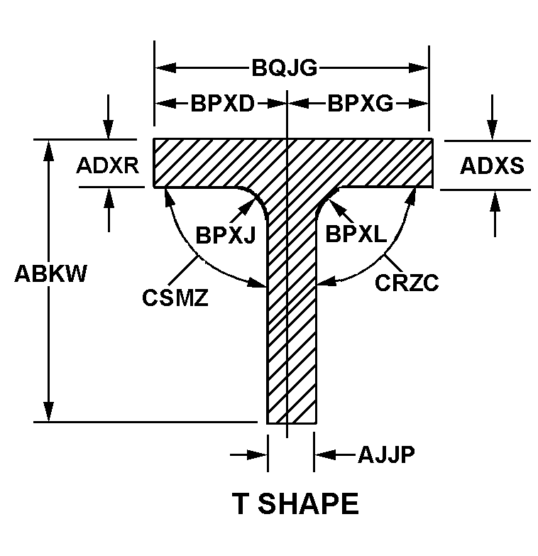
T SHAPE

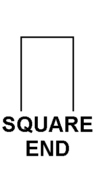
SQUARE END

SQUARE END

SQUARE END

SQUARE END

Cross Reference | NSN 9540-01-469-3308
| Part Number | Cage Code | Manufacturer |
|---|---|---|
| CVC10010-161GA | 80378 | TRIUMPH AEROSTRUCTURES, LLCDBA TRIUMPH AEROSTRUCTURES - VOUGHT |
Technical Data | NSN 9540-01-469-3308
| Characteristic | Specifications |
|---|---|
| FABRICATION METHOD | EXTRUDED |
| HEAT TREATMENT | ANNEALED |
| LENGTH | 18.800 INCHES MINIMUM AND 18.820 INCHES MAXIMUM |
| BASIC SHAPE STYLE | T SHAPE |
| OVERALL HEIGHT | 4.440 INCHES NOMINAL |
| LEFT SIDE TOP FLANGE THICKNESS | 0.115 INCHES MINIMUM AND 0.135 INCHES MAXIMUM |
| RIGHT SIDE TOP FLANGE THICKNESS | 0.115 INCHES MINIMUM AND 0.135 INCHES MAXIMUM |
| LEG THICKNESS | 0.115 INCHES MINIMUM AND 0.135 INCHES MAXIMUM |
| LEFT SIDE TOP FLANGE DISTANCE TO CENTER OF BOTH FLANGES | 2.560 INCHES NOMINAL |
| RIGHT SIDE TOP FLANGE DISTANCE TO CENTER OF BOTH FLANGES | 2.560 INCHES NOMINAL |
| FILLET RADIUS WHERE TOP LEFT FLANGE JOINS WEB FLANGE/LEG | 0.110 INCHES MINIMUM AND 0.130 INCHES MAXIMUM |
| FILLET RADIUS WHERE TOP RIGHT FLANGE JOINS WEB FLANGE/LEG | 0.110 INCHES MINIMUM AND 0.130 INCHES MAXIMUM |
| TOP FLANGE WIDTH | 5.120 INCHES NOMINAL |
| LEFT TOP INSIDE ANGLE | 90.0 DEGREES NOMINAL |
| RIGHT TOP INSIDE ANGLE | 90.0 DEGREES NOMINAL |
| FIRST TIP STYLE | 5 SQUARE END |
| FIRST TIP TAPER LENGTH | 0.690 INCHES MINIMUM AND 0.710 INCHES MAXIMUM |
| FIRST TIP THICKNESS | 0.990 INCHES MINIMUM AND 1.010 INCHES MAXIMUM |
| SECOND TIP RELATIONSHIP TO FIRST TIP | NOT IDENTICAL |
| SECOND TIP STYLE | 4 SQUARE END |
| SECOND TIP TAPER LENGTH | 0.690 INCHES MINIMUM AND 0.710 INCHES MAXIMUM |
| SECOND TIP THICKNESS | 0.990 INCHES MINIMUM AND 1.010 INCHES MAXIMUM |
| SPECIAL FEATURES | ALONG LENGTH FLANGES ON BOTH SIDES NARROW FROM NORMAL WIDTH FROM CENTER (AT 4.04 IN. FROM FIRST TIP) TO 1.01 IN. FROM CENTER (AT 6.73 IN. FROM FIRST TIP); FLANGES WIDEN FROM 1.01 IN. FROM CENTER (AT 13.18 IN. FROM FIRST TIP) TO NORMAL WIDTH (AT 15.88 IN. FROM FIRST TIP); WEAPONS SYSTEM IS AIRCRAFT, B-2 BOMBER (ATB) |